K3S High Availability with SafeKit: Install the k3s.safe Module for Failover
High Availability Quick Installation Guide for Kubernetes
This guide explains how to set up a k3s cluster for Kubernetes using SafeKit, ensuring automatic failover and synchronous replication without the need for shared storage.
For help, you can use SafeKit AI 🤖.
1. Overview
- Architecture: Uses a two-node system (Primary/Secondary).
- Data Protection: Implements real-time synchronous replication for zero data loss (RPO=0).
2. Installation
- Software: Install the SafeKit engine on both servers.
- Module: Download the pre-configured
k3s.safeapplication module.
3. Configuration
- Web Console: Configure the specific folders containing the Kubernetes files.
- Monitoring: Start monitoring and protecting the Kubernetes application.
SafeKit High Availability Limitations
Why a replication of a few Tera-bytes?
Resynchronization time after a failure (step 3)
- 1 Gb/s network ≈ 3 Hours for 1 Tera-bytes.
- 10 Gb/s network ≈ 1 Hour for 1 Tera-bytes or less depending on disk write performances.
Alternative
- For a large volume of data, use external shared storage.
- More expensive, more complex.
Why a replication < 1,000,000 files?
- Resynchronization time performance after a failure (step 3).
- Time to check each file between both nodes.
Alternative
- Put the many files to replicate in a virtual hard disk / virtual machine.
- Only the files representing the virtual hard disk / virtual machine will be replicated and resynchronized in this case.
Why a failover ≤ 32 replicated VMs?
- Each VM runs in an independent k3s module.
- Maximum of 32 k3s modules running on the same cluster.
Alternative
- Use an external shared storage and another VM clustering solution.
- More expensive, more complex.
Why a LAN/VLAN network between remote sites?
- Automatic failover of the virtual IP address with 2 nodes in the same subnet.
- Good bandwidth for resynchronization (step 3) and good latency for synchronous replication (typically a round-trip of less than 2ms).
Alternative
- Use a load balancer for the virtual IP address if the 2 nodes are in 2 subnets (supported by SafeKit, especially in the cloud).
- Use backup solutions with asynchronous replication for high latency network.
Overview of the SafeKit / Kubernetes solution
The solution is described here: Kubernetes K3s High Availability: 2-Node Synchronous Replication& Failover
Installation and configuration of the SafeKit / Kubernetes solution on Linux (k3s.safe)
1. Download packages
- Download the free version of SafeKit 8.2 on Linux (safekitlinux_xx.bin)
- Download the k3s.safe Linux module
- Download the k3sconfig.sh script
- Documentation (pptx)
Note: the k3sconfig.sh script installs K3S, MariaDB, NFS, SafeKit on 2 Linux Ubuntu 24.04 nodes.
⬇️ Download k3s.safe (Linux) >
2. First on both nodes
On 2 Linux Ubuntu 24.04 nodes, as root:
- Make sure the node has internet access (could be through a proxy)
- Copy k3sconfig.sh, k3s.safe and the safekit_xx.bin package into a directory and cd into it
- Rename the .bin file as “safekit.bin”
- Make sure k3sconfig.sh and safekit.bin are executable.
- Edit the k3sconfig.sh script and customize the environment variables according to your environment (including a virtual IP)
- Execute on both nodes:
./k3sconfig.sh prereq
The script will:
- Install required debian packages: alien, nfs-kernel-server, nfs-common, mariadb-server
- Secure mariadb installation
- Create directories for file replication
- Prepare the NFS server for sharing replicated directories
- Install SafeKit
3. On the first node
Execute on the first node: ./k3sconfig.sh first
The script will:
- Create the K3S configuration database and the k3s user
- Create the replicated storage volume file (sparse file) and format it as an xfs filesystem
- Create the safekit cluster configuration and apply it
- Install and configure the k3s.safe module on the cluster
- Start the k3s module as “prim” on the first node
- Download, install and start k3s
- Download and install nfs-subdir-external-provisioner Helm chart
- Display K3S token (to be used during second node installation phase)
4. On the second node
Execute on the second node: ./k3sconfig.sh second <token>
is the string displayed at the end of the “k3sconfig.sh first” execution on the first node
The script will:
- Make sure the k3s module is started as prim on the first node
- Install k3s on the second node
- Start the k3s module
5. Check that the k3s SafeKit module is running on both nodes
Check with this command on both nodes: /opt/safekit/safekit –H "*" state
The reply should be similar to the image.
/opt/safekit/safekit –H "*" state
---------------- Server=http://10.0.0.20:9010 ----------------
admin action=exec
--------------------- k3s State ---------------------

  Local  (127.0.0.1)    : PRIM (Service : Available)(Color : Green)
Success
---------------- Server=http://10.0.0.21:9010 ----------------
admin action=exec
--------------------- k3s State ---------------------

  Local  (127.0.0.1)    : SECOND (Service : Available)(Color : Green)
Success
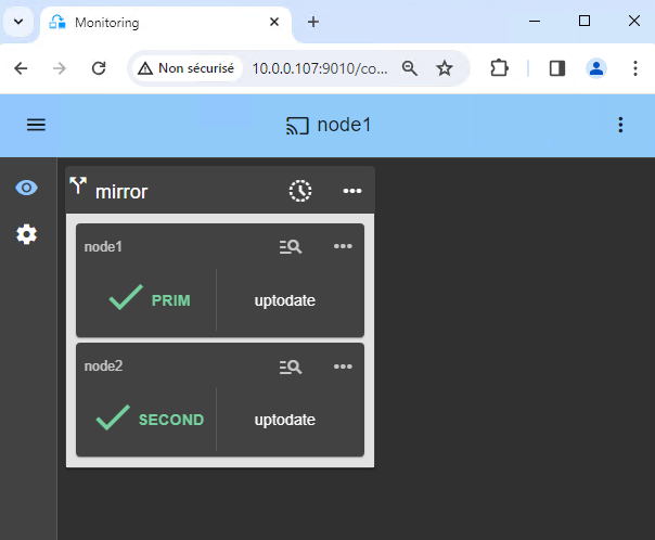
6. Start the SafeKit web console to administer the cluster
- Connect a browser to the SafeKit web console url
http://server0-IP:9010. - You should see a page similar to the image.
- Check with Linux command lines that K3S is started on both nodes (started in
start_primandstart_second) and that MariaDB is started on the primary node (started instart_prim).
7. Testing
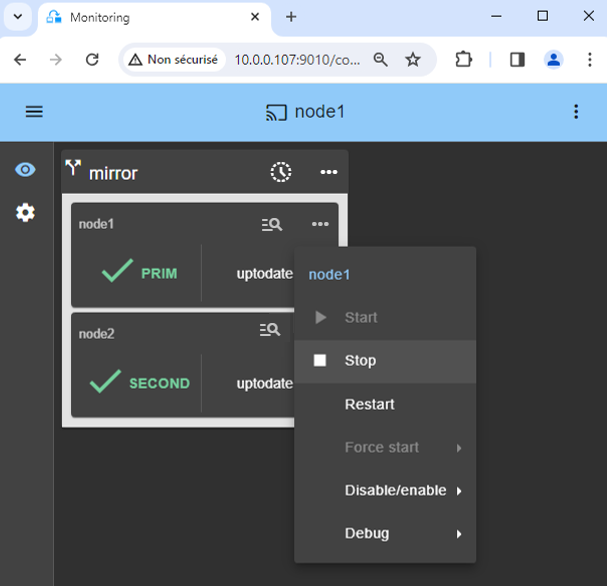
- Stop the PRIM node by scrolling down its contextual menu and clicking
Stop. - Verify that there is a failover on the SECOND node which should become ALONE (green).
- And with command lines on Linux, check the failover of services (stopped on node 1 in the
stop_primscript and started on node 2 in thestart_primscript). MariaDB and K3S should run on node2.
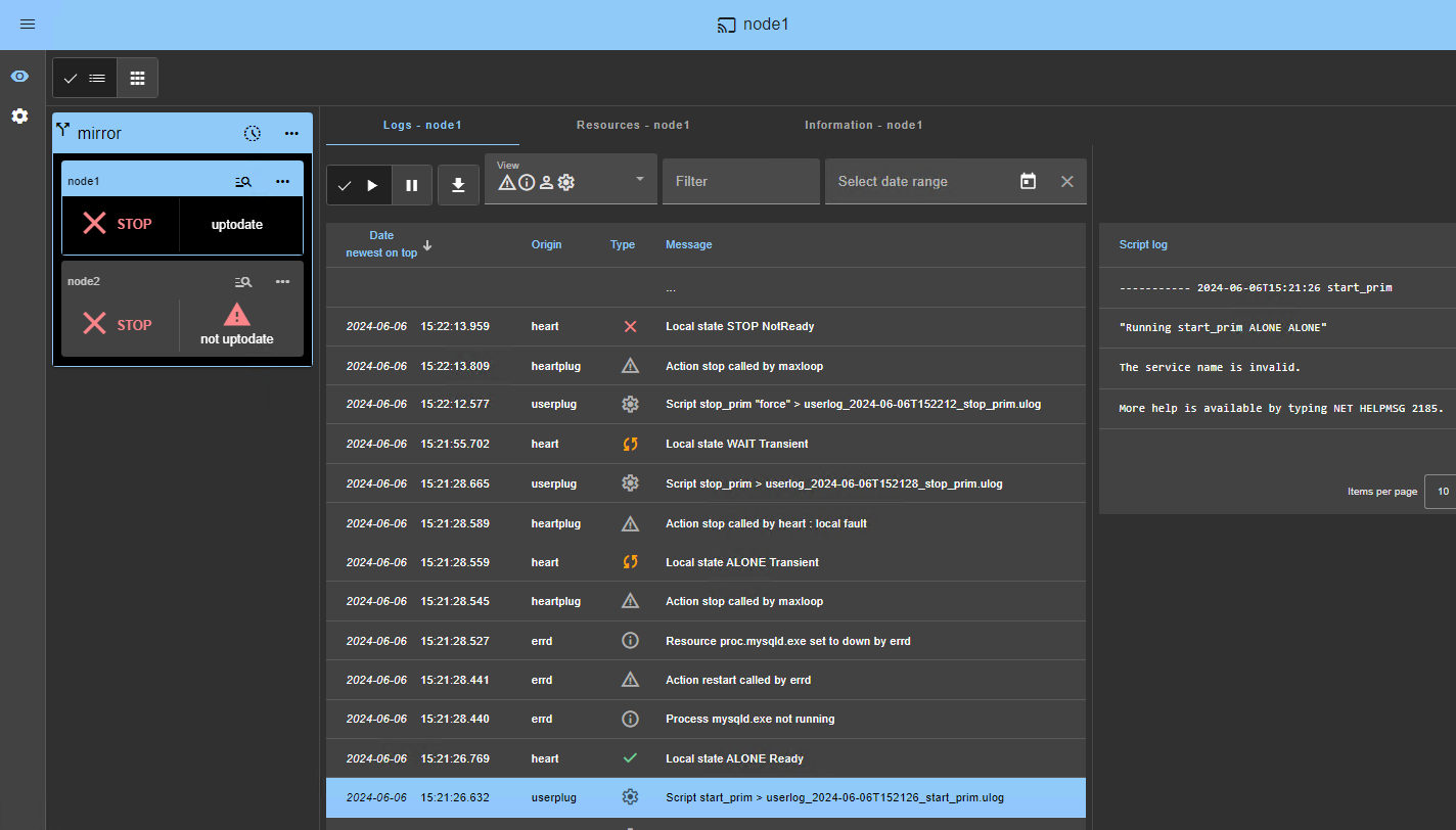
 If ALONE (green) is not reached on node2, analyze why with the module log of node 2.
- click on
node2to display the module log. - example of a SQL Server module log where the service name in
start_primis invalid. The sqlserver.exe process is monitored but as it is not started, at the end the module stops.
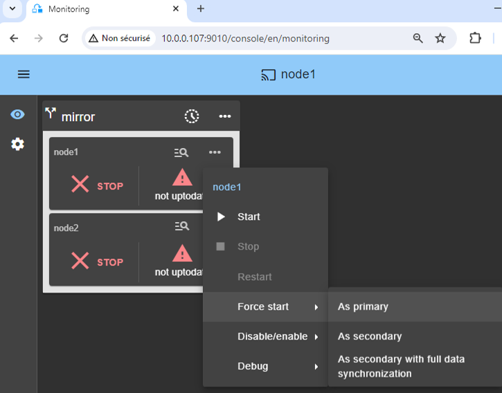
If everything is okay, initiate a start on node1, which will resynchronize the replicated directories from node2.If things go wrong, stop node2 and force the start as primary of node1, which will restart with its locally healthy data at the time of the stop.

8. Try the cluster with a Kubernetes application like WordPress
You have the example of a WordPress installation in the image: a web portal with a backend database implemented by pods.
You can deploy your own application in the same way.
WordPress is automatically highly available:
- with its data (php + database) in persistent volumes replicated in real-time by SafeKit
- with a virtual IP address to access the WordPress site for users
- with automatic failover and automatic failback
Notes:
The WordPress chart defines a load balanced service that listens on <service.port> and <service.httpsport> ports.
WordPress is accessible through the url:
http://<virtual-ip>:<service.port>.The virtual IP is managed by SafeKit and automatically switched in case of failover.
By default, K3S implements load balancers with Klipper.
Klipper listens on
:<service.port> and routes the TCP/IP packets to the IP address and port of the WordPress pod that it has selected. $ export KUBECONFIG=/etc/rancher/k3s/k3s.yaml $ helm repo add bitnami https://charts.bitnami.com/bitnami $ helm install my-release bitnami/wordpress –set global.storageClass=nfs-client –set service.ports.http=8099,service.ports.https=4439
The previous helm command should download the WordPress image from registry-1.docker.io. You may encounter authentication issues on registry-1.docker.io. In this case, you should:
create
/etc/rancher/k3s/registries.yamlon both nodes with inside:configs: "registry-1.docker.io": auth: username: your_user_name password: your_password tls: insecure_skip_verify: truestop and start k3s to take it into account, with
systemctl stop k3sandsystemctl start k3s.Execute
helm registry login -u your_user_name docker.io, then enter your password
9. Support
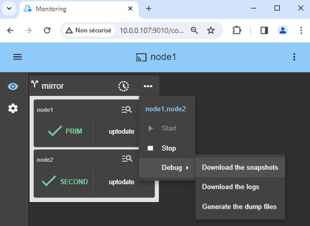
- For getting support, take 2 SafeKit
Snapshots(2 .zip files), one for each node.
10. If necessary, configure a splitbrain checker
See below “What are the different scenarios in case of network isolation in a cluster?” to know if you need to configure a splitbrain checker.
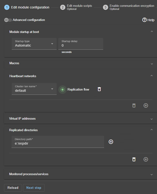
In the module configuration, click on
Advanced Configuration(see image) to edituserconfig.xml.Declare the splitbrain checker by adding in the
<check>section ofuserconfig.xml:<service> ... <check> ... <splitbrain ident="witness" exec="ping" arg="witness IP"/> </check>Save and applythe new configuration to redeploy the modified userconfig.xml file on both nodes (module must be stopped on both nodes to save and apply).
Parameters :
ident="witness"identifies the witness with a resource name:splitbrain.witness. You can change this value to identify the witness.exec="ping"references the ping code to execute. Do not change this value.arg="witness IP"is an argument for the ping. Change this value with the IP of the witness (a robust element, typically a router).
What are the different scenarios in case of network isolation in a cluster?
A single network
When there is a network isolation, the default behavior is:
- as heartbeats are lost for each node, each node goes to ALONE and runs the application with its virtual IP address (double execution of the application modifying its local data),
- when the isolation is repaired, one ALONE node is forced to stop and to resynchronize its data from the other node,
- at the end the cluster is PRIM-SECOND (or SECOND-PRIM according the duplicate virtual IP address detection made by Windows).
Two networks with a dedicated replication network
When there is a network isolation, the behavior with a dedicated replication network is:
- a dedicated replication network is implemented on a private network,
- heartbeats on the production network are lost (isolated network),
- heartbeats on the replication network are working (not isolated network),
- the cluster stays in PRIM/SECOND state.
A single network and a splitbrain checker
When there is a network isolation, the behavior with a split-brain checker is:
- a split-brain checker has been configured with the IP address of a witness (typically a router),
- the split-brain checker operates when a server goes from PRIM to ALONE or from SECOND to ALONE,
- in case of network isolation, before going to ALONE, both nodes test the IP address,
- the node which can access the IP address goes to ALONE, the other one goes to WAIT,
- when the isolation is repaired, the WAIT node resynchronizes its data and becomes SECOND.
Note: If the witness is down or disconnected, both nodes go to WAIT and the application is no more running. That’s why you must choose a robust witness like a router.
Demonstration of the SafeKit mirror solution
SafeKit Video: Application-Level Clustering (8:47)
In this video, discover how SafeKit implements a mirror HA cluster without the complexity of a SAN. While this demonstration uses Microsoft SQL Server, the solution works identically for other databases and applications.
Chapters
- 2 nodes with SQL Server (0:32)
- Configure the cluster and the mirror.safe module (3:58)
- Start and test SQL replication, migration, failover on crash (4:17)
Step-by-Step Implementation
- Read the guide on setting up a mirrored cluster on Windows
- Read the guide on setting up a mirrored cluster on Linux
&amp;amp;amp;amp;lt;br /&amp;amp;amp;amp;gt;
🔍 SafeKit High Availability Navigation Hub
Explore SafeKit: Features, technical videos, documentation, and free trial
| Resource Type | Description | Direct Link |
|---|---|---|
| Key Features | Why Choose SafeKit for Simple and Cost-Effective High Availability? | See Why Choose SafeKit for High Availability |
| Use Cases | Explore How SafeKit Ensures the High Availability of Critical Infrastructure | See All Use Cases (OEM Software, Edge Servers, SCADA, and more) |
| Deployment Model | All-in-One SANless HA: Shared-Nothing Software Clustering | See SafeKit All-in-One SANless HA |
| HA Strategies | SafeKit: Infrastructure (VM) vs. Application-Level High Availability | See SafeKit HA & Redundancy: VM vs. Application Level |
| Technical Specifications | Technical Limitations for SafeKit Clustering | See SafeKit High Availability Limitations |
| Proof of Concept | SafeKit: High Availability Configuration & Failover Demos | See SafeKit Failover Tutorials |
| Architecture | How the SafeKit Mirror Cluster works (Real-Time Replication & Failover) | See SafeKit Mirror Cluster: Real-Time Replication & Failover |
| Architecture | How the SafeKit Farm Cluster works (Network Load Balancing & Failover) | See SafeKit Farm Cluster: Network Load Balancing & Failover |
| Competitive Advantages | Comparison: SafeKit vs. Traditional High Availability (HA) Clusters | See SafeKit vs. Traditional HA Cluster Comparison |
| Technical Resources | SafeKit High Availability: Documentation, Downloads & Trial | See SafeKit HA Free Trial & Technical Documentation |
| Pre-configured Solutions | SafeKit Application Module Library: Ready-to-Use HA Solutions | See SafeKit High Availability Application Modules |